Advanced Assembly
Combine motors, printed parts, and PCBs inside an assembly.device. These examples show how named mounting faces connect a NEMA17 to a printed bracket, then place its controller on the same base.
Start with the index.tsx tab to see the assembly connections. The other tabs contain the complete geometry and controller components; the editor button opens all the files together.
Mount a motor to a printed bracket
The bracket has a base, an upright with a shaft opening, and two supporting ribs. Its four motor holes are 3.2 mm in diameter on the NEMA17's 31 mm square pattern. A 23 mm opening clears the motor's 22 mm pilot.
mountedTo="BRACKET.motor" selects the bracket's named attachment face. mountFace="frontface" selects the motor's shaft-side body face. Core mates those two faces, positioning and orienting the motor without manual CAD offsets.
import { assembly } from "tscircuit"
import { MotorBracket } from "./motor-bracket"

export default () => (
  <assembly.device>
    <assembly.printedpart name="BRACKET" jscad={<MotorBracket />} />
    <assembly.motor
      name="MOTOR"
      standard="nema17"
      mountedTo="BRACKET.motor"
      mountFace="frontface"
    />
  </assembly.device>
)
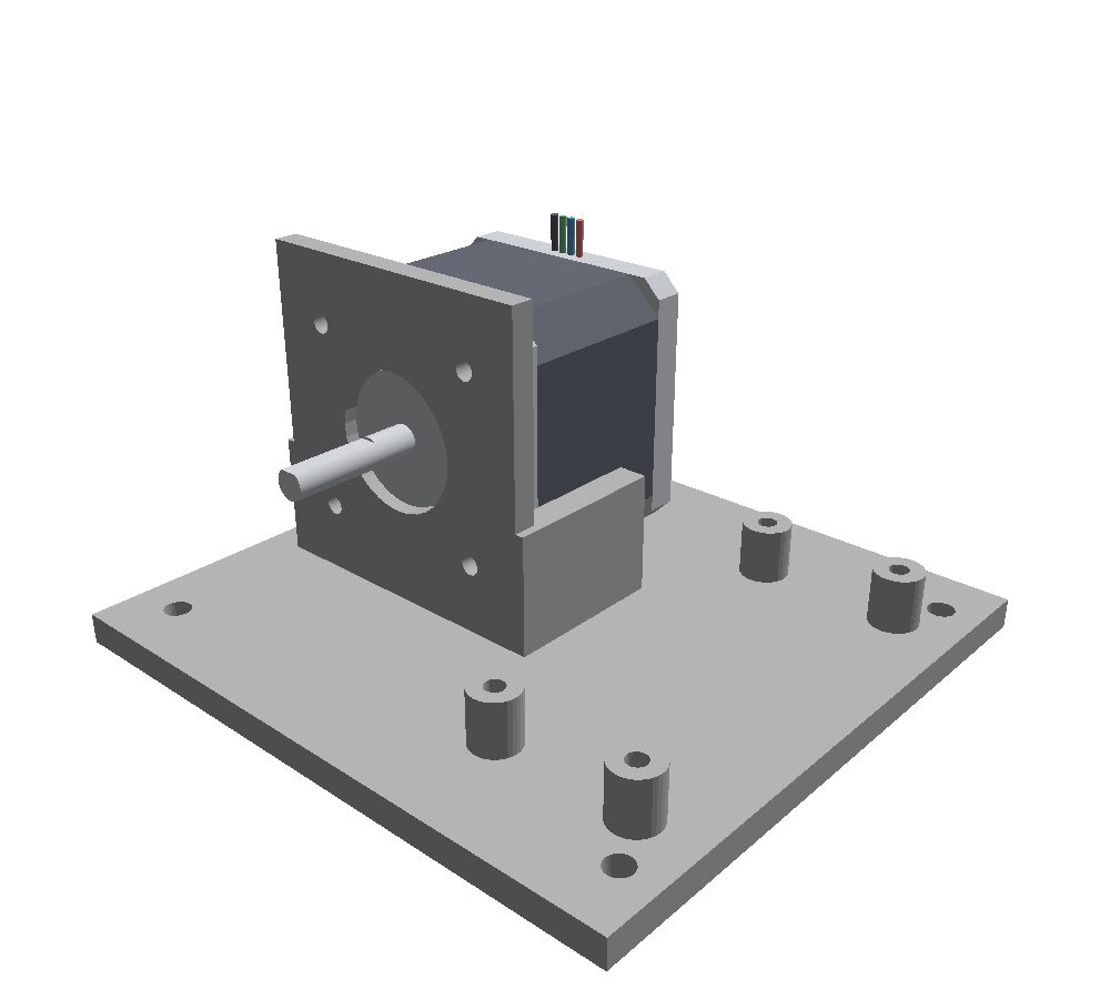
The motor-bracket.tsx tab defines the attachment face alongside its geometry:
<jscad.translate offset={[0, 0, 32]}>
  <jscad.rotate angles={[0, -Math.PI / 2, 0]}>
    <jscad.rectangle name="motor" size={[42, 42]} reference />
  </jscad.rotate>
</jscad.translate>
This reference is centered 32 mm above the base's underside and faces −X. Mating the motor's frontface to it points the shaft along +X, through the upright. reference rectangles describe attachment frames; they do not add material to the printed part.
Face origins coincide, outward normals oppose, and the faces' in-plane X directions align. Rotating the reference therefore controls the motor's rotation around its shaft as well as its shaft direction. Omit shaftFacingDirection when using mountedTo and mountFace.
Add a controller to the same base
The bracket also defines a controller face at the tips of four posts. Mount a board to that face, using the same hole coordinates for the posts and PCB.
import { assembly } from "tscircuit"
import { MotorBracket } from "./motor-bracket"
import { MotorController } from "./motor-controller"

export default () => (
  <assembly.device>
    <assembly.printedpart name="BRACKET" jscad={<MotorBracket />} />
    <assembly.motor
      name="MOTOR"
      standard="nema17"
      mountedTo="BRACKET.motor"
      mountFace="frontface"
    />
    <MotorController
      mountedTo="BRACKET.controller"
      pcbX={-10}
      pcbY={50}
    />
  </assembly.device>
)
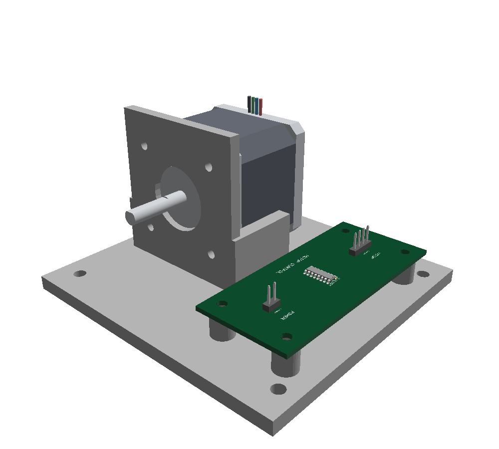
MotorController forwards its mounting props to <board>. The controller face is at [-10, 50, 14] in the bracket's local coordinates; the board uses pcbX={-10} and pcbY={50} to preserve that layout. Its four 3.2 mm holes use the same 64 × 24 mm pattern as the posts. The post tips are 14 mm above the base's underside, including the 5 mm base plate.
Mounting keeps the PCB in the XY plane at Z = 0. Core moves the connected bracket and motor around it: in this example, the bracket's underside moves to Z = −14.8 mm so the posts touch the bottom of the 1.6 mm PCB. No manual Z offset is needed in the assembly code.
The four-pin J_MOTOR header reserves a connection for the motor's two windings. The driver package and headers demonstrate board placement; this example has no routed driver circuit or cable connection. Replace them with your controller circuitry when adapting the assembly.
Adjust the mounting
| Change | How |
|---|---|
| Separate a motor from its bracket | Add mountGap="2mm" to assembly.motor. The gap follows the target face's outward normal. |
| Use the rear of the motor | Set mountFace="backface" and provide a bracket with the appropriate rear mounting geometry. |
| Change the motor's direction or rotation around the shaft | Rotate the bracket's reference rectangle. JSCAD angles are in radians. |
| Raise the controller | Move both the post tips and the controller reference to the new height. |
| Put a spacer between a motor and a PCB | See the motor–spacer–board example. |
frontface is the shaft-side body plane, excluding the pilot and shaft. backface is the body plane opposite the shaft. Face mounting does not generate screw holes or check collisions; model the required holes and clearances in the printed part.
References resolve within the nearest assembly.device, and declaration order does not matter. A connected assembly can have one PCB anchor. Missing or ambiguous targets, cycles, and a PCB mounted to a tilted face report errors. For assemblies containing a face-mounted motor, author rotation in the reference geometry rather than using board mountRotation or mountRotationAnchor.
These examples require @tscircuit/core 0.0.2085 or later, with @tscircuit/props 0.0.687 or later. For all available props, see assembly.motor and assembly.printedpart.