<assembly.cable />
assembly.cable connects two endpoints inside an assembly.device. Give it a name, from, and to. Core infers a compatible cable and its route from the connectors' positions and orientations, then renders its wires and plugs in 3D.
Connect a motor to its controller
Use wireConnection="jst-ph-6" on assembly.motor to expose the wireside connector. Match it with a six-pin JST PH connector on the board. The cable standard is inferred, so this example does not need a standard prop:
import { assembly } from "tscircuit"

export default () => (
  <assembly.device>
    <assembly.motor name="MOTOR" standard="nema17"
      wireConnection="jst-ph-6" />
    <board name="CONTROLLER" width={44} height={34}
      pcbX={85} routingDisabled>
      <connector name="J_MOTOR" standard="jst_ph" pinCount={6}
        footprint="jst6_ph" pcbX={-18} pcbRotation={90} />
    </board>
    <assembly.cable name="MOTOR_CABLE"
      from="MOTOR.wireside" to=".CONTROLLER > .J_MOTOR" />
  </assembly.device>
)
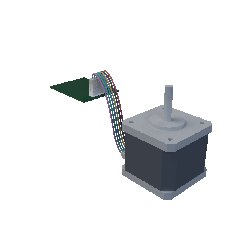
The board connector sits at the edge facing the motor, so the cable approaches outside the PCB instead of passing through it.
MOTOR.wireside is the named motor endpoint. .CONTROLLER > .J_MOTOR selects the connector inside that board. Mounting and cabling are independent: use mountedTo to place parts, and keep the same cable references when their positions change. See the printed spacer and bracket-mounted controller examples.
The six-pin PH termination is a supported model configuration, not a requirement for every NEMA17 motor. Choose the connector and winding pinout for your actual motor. A physical cable does not create electrical traces or map pins.
Connect two boards with USB-C
Place each USB-C port on its own board and select each endpoint through its board name. standard="usb_c" explicitly requests a USB-C-to-USB-C cable. It can also be omitted when both endpoints use standard="usb_c":
import { assembly } from "tscircuit"

export default () => (
  <assembly.device>
    <board name="HOST" width={32} height={28} pcbX={-60}
      routingDisabled>
      <connector name="J_USB" standard="usb_c" footprint="usbcmidmount"
        pcbX={13} pcbRotation={90} />
    </board>
    <board name="CONTROLLER" width={32} height={28} pcbX={60}
      routingDisabled>
      <connector name="J_USB" standard="usb_c" footprint="usbcmidmount"
        pcbX={-13} pcbRotation={270} />
    </board>
    <assembly.cable name="USB" standard="usb_c"
      from=".HOST > .J_USB" to=".CONTROLLER > .J_USB" />
  </assembly.device>
)
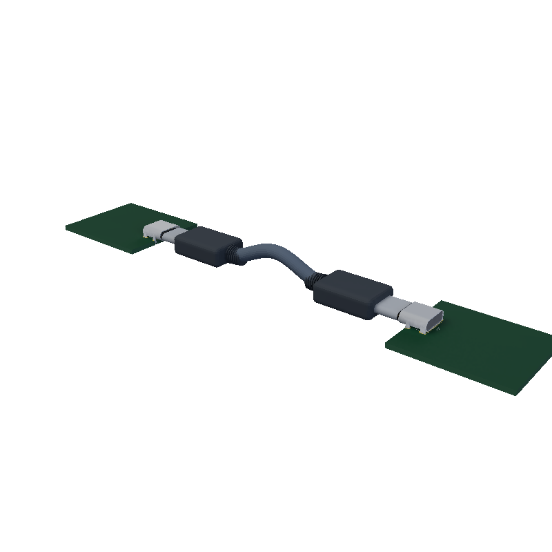
Cable properties
| Property | Type | Description |
|---|---|---|
name | string | Required cable name. Use a different name for each cable. |
from | string | Required starting endpoint: a connector selector or a motor's wireside reference. |
to | string | Required ending endpoint, distinct from from. |
standard | "usb_c" | Optional USB-C preset. Omit to infer USB-C, JST SH (1 mm pitch), or JST PH (2 mm pitch) from the endpoints. |
For JST cables, both connectors must have the same standard and pinCount. Select a matching footprint, such as jst6_ph for a six-pin PH header. Incompatible standards, different pin counts, and missing or ambiguous endpoints report errors. Endpoints resolve within the nearest assembly.device, including components declared later.
Add one assembly.cable for each physical cable; several cables can share a device. Each produces an independent cad_cable path in Circuit JSON. The initial route includes connector exit directions and a clearance arch. It does not perform obstacle avoidance or calculate gravity sag, so inspect the rendered path when placing enclosures and nearby parts. There are no length or route-hint props.
These examples require @tscircuit/core 0.0.2088 or later and circuit-json-to-gltf 0.0.144 or later. When using the tscircuit package, use a release that includes those versions.