Building a 3x5 LED Matrix
Overview
This tutorial will walk you through building a 3x5 LED matrix controlled by a Raspberry Pi Pico using tscircuit.
Objectives of Building an LED Matrix
Some practical applications of building an LED Matrix include:
- Signage - Building signs for events, products, etc.
- Data Visualization Tool - Displaying real-time data metrics like GitHub contributions, website traffic, or temperature readings through color intensity
- Interactive Notification System - Creating a physical notification system for emails, social media, or calendar events with customizable brightness levels
LED Matrix Requirements
- The LED matrix must be WiFi-controllable
- The matrix layout pattern must be grid-based
- Each LED should be individually controllable for brightness and color
System Diagram
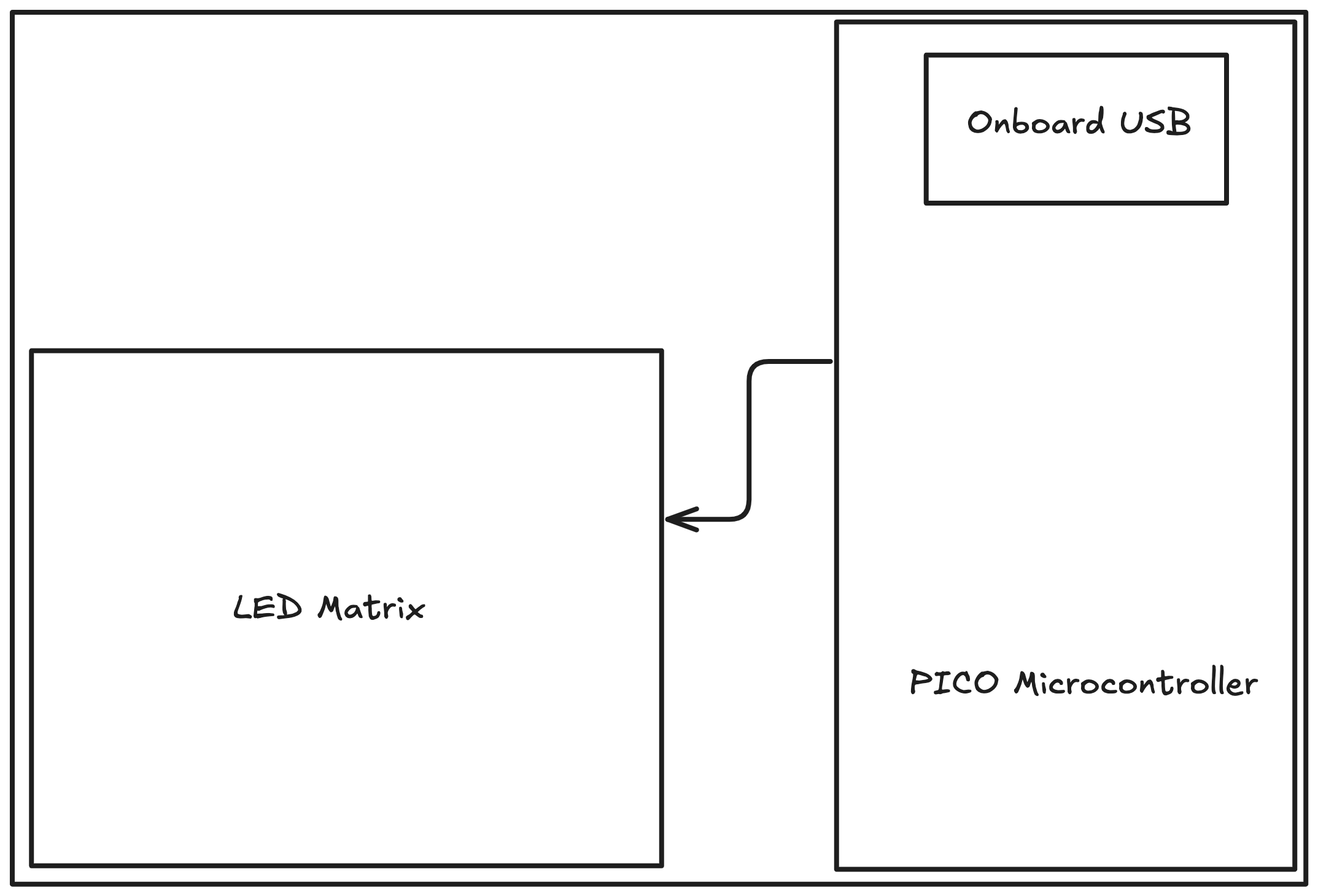
The matrix connects to the Pico microcontroller via a data chain. The Pico connects to WiFi through the PICO_W module.
The components and connections between them are shown in the diagram below:
Schematic Capture
Let's import the Pico microcontroller and LED components by following the steps in the Importing from JLCPCB section.
We will follow the following steps to build the circuit step by step:
- Import the Pico microcontroller Schematic
- Import the LED Schematic
- Chain two LEDs together
- Chain many LEDs together
- Connect the Pico to the LED matrix
Pico Schematic
Schematic of the Pico microcontroller imported from JLCPCB is shown below:
LED Schematic
We are using IC LEDs (specifically WS2812B), which have an RGB LED and control chip integrated into the same package. These IC LEDs offer several advantages over traditional RGB LEDs:
- Simplified Wiring - Only 4 pins needed (VDD, GND, Data In, Data Out) compared to 4+ pins for traditional RGB LEDs
- Serial Communication - LEDs can be daisy-chained together, requiring only one data pin from the microcontroller
- Individual Control - Each LED in the chain can be controlled independently for color and brightness
Chaining Two LEDs together
To connect two LEDs together, we need to connect the data output DO of the first LED to the data input DI of the second LED. This creates a chain of LEDs.
import { WS2812B_2020 as LedWithIc } from "@tsci/seveibar.WS2812B_2020"

export default () => (
<board>
 {/* First LED */}
  <LedWithIc
    schX={0}
    schY={0}
    name={"LED1"}
  />
  {/* Second LED */}
  <LedWithIc
    schX={5}
    schY={0}
    name={"LED2"}
  />

  {/* Connecting the LEDs to GND and VDD */}
  <trace from={".LED1 .GND"} to="net.GND" />
  <trace from={".LED1 .VDD"} to="net.V5" />

  <trace from={".LED2 .GND"} to="net.GND" />
  <trace from={".LED2 .VDD"} to="net.V5" />

  {/* Connecting the LEDs together */}
  <trace from={".LED1 .DO"} to={".LED2 .DI"} />
</board>
)
Connecting Pico to the LED Matrix
The Pico is connected to the LED matrix via a general purpose input/output (GPIO) pin in this example we are using GP6,
and the other pins of the Pico are connected to ground.
import { usePICO_W } from "@tsci/seveibar.PICO_W"
import { WS2812B_2020 as LedWithIc } from "@tsci/seveibar.WS2812B_2020"

export default () => {
const U1 = usePICO_W("U1")
return (
  <board
    width="60mm"
    height="60mm"
  >
    {/* Pico microcontroller */}
    <U1 />

    {/* LED */}
    <LedWithIc
      name={"LED1"}
      schX={-5}
    />

    {/* Connecting the LED to GND and VDD */}
    <trace from={".LED1 .GND"} to="net.GND" />
    <trace from={".LED1 .VDD"} to="net.V5" />

    {/* Connecting the LED to the Pico GP6 pin */}
    <trace from=".LED1 .DI" to={U1.GP6_SPI0SCK_I2C1SDA} />

    {/* Connecting the Pico to GND */}
    <trace from={U1.GND1} to="net.GND" />
    <trace from={U1.GND2} to="net.GND" />
    <trace from={U1.GND3} to="net.GND" />
    <trace from={U1.GND4} to="net.GND" />
    <trace from={U1.GND5} to="net.GND" />
    <trace from={U1.GND6} to="net.GND" />
    <trace from={U1.GND7} to="net.GND" />

    {/* Connecting the Pico to the power supply */}
    <trace from={U1.VBUS} to="net.V5" />
  </board>
)
}
Chaining many LEDs together
LED Matrix Layout
We can connect multiple LEDs together by chaining them, but doing this for a large number of LEDs would be tedious. Luckily, tscircuit has a helper function to create a grid of components. We will be using that helper function to create our matrix layout.
Here we are using the grid function to create a 3x5 LED matrix. The grid function takes in the number of columns and rows, and the spacing between the components.
import { WS2812B_2020 as LedWithIc } from "@tsci/seveibar.WS2812B_2020"
import { grid } from "@tscircuit/math-utils"

export default () => {
return (
  <board width="65mm" height="52mm" routingDisabled>
    {/* 3x5 LED matrix */}
    {grid({ cols: 3, rows: 5, xSpacing: 8, ySpacing: 5, offsetX: 20, offsetY: 5 }).map(
      ({ center, index }) => {
        const ledName = "LED" + (index + 1)
        const prevLedName = index > 0 ? "LED" + (index) : null
        return (
          <>
            {/* LED */}
            <LedWithIc schX={center.x/2} schY={5 + center.y/2} name={ledName} />

            {/* Connecting the LED to GND and VDD */}
            <trace from={".LED" + (index + 1) + " .GND"} to="net.GND" />
            <trace from={".LED" + (index + 1) + " .VDD"} to="net.V5" />

            {/* Connecting the LED to the previous LED */}
            {prevLedName && <trace from={".LED" + (index) + " .DO"} to={".LED" + (index + 1) + " .DI"} />}
          </>
        )
      }
    )}
  </board>
)
}
Connecting the Pico to the LED matrix
Here we are merging all the learnings from the previous examples to create a complete circuit. The Pico is connected to the LED matrix via the GP6 pin, and the other pins of the Pico are connected to ground.
The GP6 pin is connected to the data input DI of the first LED, and the data output DO of each LED is connected to the data input DI of the next LED in the chain.
While connecting the LEDs together, we are also connecting the GND and VDD pins of the LEDs to ground and 5V supply respectively.
Complete circuit is shown below:
import { usePICO_W } from "@tsci/seveibar.PICO_W"
import { WS2812B_2020 as LedWithIc } from "@tsci/seveibar.WS2812B_2020"
import { grid } from "@tscircuit/math-utils"

export default () => {
const U1 = usePICO_W("U1")
return (
  <board width="60mm" height="60mm" routingDisabled>
    {/* Pico microcontroller */}
    <U1 />

    {/* LED matrix */}
    {grid({ cols: 3, rows: 5, xSpacing: 8, ySpacing: 5, offsetX: 20 }).map(
      ({ center, index }) => {
        const ledName = "LED" + (index + 1)
        const prevLedName = index > 0 ? "LED" + (index) : null
        return (
          <>
            {/* LED */}
            <LedWithIc schX={center.x/2} schY={5 + center.y/2} name={ledName} />

            {/* Connecting the LED to GND and VDD */}
            <trace from={".LED" + (index + 1) + " .GND"} to="net.GND" />
            <trace from={".LED" + (index + 1) + " .VDD"} to="net.V5" />

            {/* Connecting the LED to the previous LED */}
            {prevLedName && <trace from={".LED" + (index) + " .DO"} to={".LED" + (index + 1) + " .DI"} />}
          </>
        )
      }
    )}

    {/* Connecting the Pico to the LED matrix using GP6 pin */}
    <trace from={U1.GP6_SPI0SCK_I2C1SDA} to={".LED1 .DI"} />

    {/* Connecting the Pico to GND */}
    <trace from={U1.GND1} to="net.GND" />
    <trace from={U1.GND2} to="net.GND" />
    <trace from={U1.GND3} to="net.GND" />
    <trace from={U1.GND4} to="net.GND" />
    <trace from={U1.GND5} to="net.GND" />
    <trace from={U1.GND6} to="net.GND" />
    <trace from={U1.GND7} to="net.GND" />
  </board>
)
}
PCB Layout
We can translate our schematic into a PCB layout by specifying the physical positions of components on the board.
Here we are adding the positions of the components on the PCB:
- Pico microcontroller is added at
pcbX={-15} pcbY={0}with a rotation of90deg(Rotation is needed for the Pico to be in the correct orientation) - LEDs are added at positions calculated by the grid function with a spacing of
8mmhorizontally and5mmvertically
import { usePICO_W } from "@tsci/seveibar.PICO_W"
import { WS2812B_2020 as LedWithIc } from "@tsci/seveibar.WS2812B_2020"
import { grid } from "@tscircuit/math-utils"

export default () => {
const U1 = usePICO_W("U1")
return (
  <board width="65mm" height="60mm" routingDisabled>
    {/* Pico microcontroller */}
    <U1 pcbRotation="90deg" pcbX={-15} pcbY={0} />

    {/* LED matrix */}
    {grid({ cols: 3, rows: 5, xSpacing: 8, ySpacing: 5, offsetX: 20, offsetY: 5 }).map(
      ({ center, index }) => {
        const ledName = "LED" + (index + 1)
        const prevLedName = index > 0 ? "LED" + (index) : null
        return (
          <>
            {/* LED */}
            <LedWithIc schX={center.x/2} schY={5 + center.y/2} name={ledName} pcbX={center.x} pcbY={center.y} />

            {/* Connecting the LED to GND and VDD */}
            <trace from={".LED" + (index + 1) + " .GND"} to="net.GND" />
            <trace from={".LED" + (index + 1) + " .VDD"} to="net.V5" />

            {/* Connecting the LED to the previous LED */}
            {prevLedName && <trace from={".LED" + (index) + " .DO"} to={".LED" + (index + 1) + " .DI"} />}
          </>
        )
      }
    )}

    {/* Connecting the Pico to the LED matrix using GP6 pin */}
    <trace from={U1.GP6_SPI0SCK_I2C1SDA} to={".LED1 .DI"} />

    {/* Connecting the Pico to GND */}
    <trace from={U1.GND1} to="net.GND" />
    <trace from={U1.GND2} to="net.GND" />
    <trace from={U1.GND3} to="net.GND" />
    <trace from={U1.GND4} to="net.GND" />
    <trace from={U1.GND5} to="net.GND" />
    <trace from={U1.GND6} to="net.GND" />
    <trace from={U1.GND7} to="net.GND" />
  </board>
)
}
Check out this circuit in our Playground.
Ordering the PCB
You can order this PCB by downloading the fabrication files and uploading them to JLCPCB. Follow the instructions from here.
Controlling the LED Matrix
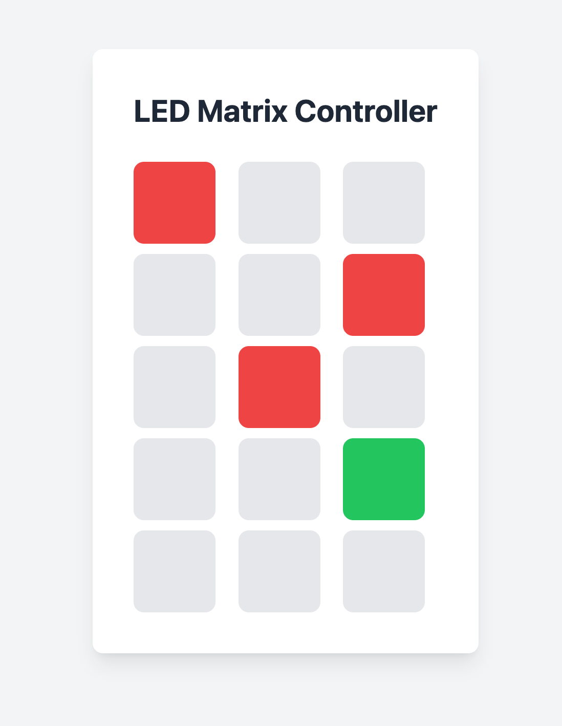
The LED matrix can be controlled through a simple web interface that provides a visual grid for controlling individual LEDs. The control system includes:
 |  |
-
Web Interface: A 3x5 grid interface where clicking each cell cycles through:
- Off (Gray)
- Red
- Green
- Blue
-
API Integration: The matrix state can be controlled and monitored through REST endpoints, making it easy to integrate with other applications.
-
Pico W Connection: The matrix connects to WiFi using the Pico W's wireless capabilities, allowing for remote control through the web interface.
The complete implementation, including the web interface and Pico W code, is available in our LED Matrix Server repository.